Structured Cabling That Protects Network Uptime
Structured Cabling That Protects Network Uptime
Structured cabling gives networks, security, voice, and building systems a tested physical foundation built for uptime, expansion, and serviceability.
A network outage rarely begins with a dramatic equipment failure. More often, it starts with an undocumented cable, an overloaded pathway, a poorly terminated fiber strand, or a move that disrupted a connection no one knew was carrying a critical system. Structured cabling is the physical layer that prevents those small failures from becoming operational downtime.
For a manufacturing plant, hospital, school district, utility site, airport, or multi-building campus, cabling is not simply a construction line item. It supports the systems that keep people safe, information moving, and operations under control. Network switches, wireless access points, security cameras, access control panels, paging, AV, SCADA, and building systems all depend on infrastructure that was designed, installed, tested, and documented correctly.
What Structured Cabling Actually Includes
Structured cabling is a standards-based approach to building a communications infrastructure rather than installing individual cables one project at a time. It creates an organized, repeatable system that connects equipment rooms, telecommunications rooms, work areas, field devices, and building pathways.
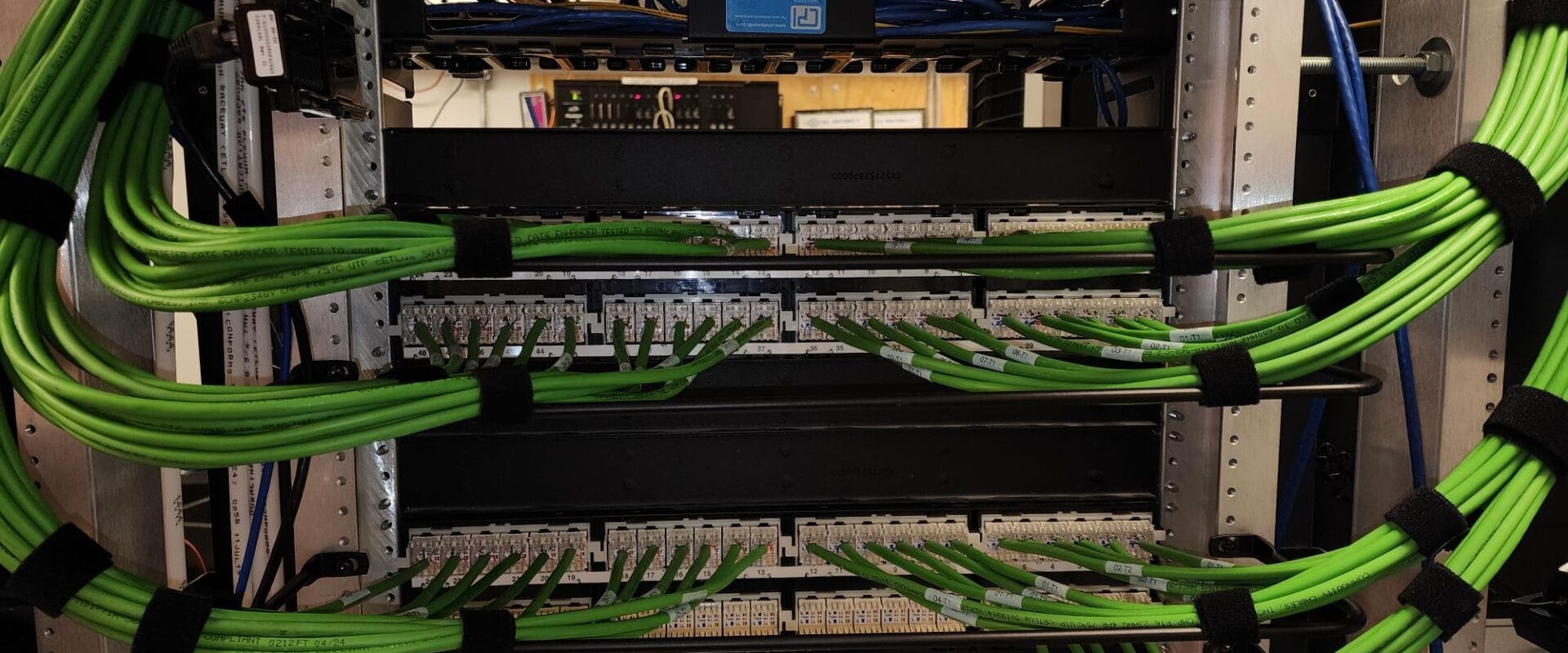
A complete system typically includes copper horizontal cabling, fiber optic backbone cabling, patch panels, racks, cabinets, pathways, grounding and bonding, labeling, termination hardware, and test documentation. The components matter, but the system design matters more. A Category 6A cable installed with improper bend radius, excessive untwist at termination, or inadequate pathway support will not deliver the performance its label suggests.
The applicable standard depends on the facility and scope. ANSI/TIA standards establish expectations for topology, performance, administration, pathways, grounding, and testing. Local code requirements, fire ratings, manufacturer installation requirements, and the operating environment also shape the final design. Industrial spaces, for example, may require protection from vibration, moisture, chemicals, electromagnetic interference, or physical damage that would not be a concern in a conventional office.
Structured Cabling Is an Uptime Decision
Active equipment gets most of the attention during a network refresh. Switches, firewalls, servers, and wireless platforms have visible features and defined replacement cycles. Cabling is less visible, but it remains in place through multiple generations of electronics. A poorly planned installation can limit the performance of every device connected to it for years.
That is why cabling should be evaluated as a long-term operational asset. The right design allows a facilities or IT team to add capacity, relocate users, replace active equipment, and isolate faults without turning every change into a disruptive investigation. The wrong design creates a patchwork of extensions, unlabeled runs, crowded trays, and single points of failure that only become apparent during an outage.
Consider a campus adding cameras, wireless coverage, door access, and connected production equipment over several years. Each system may be approved separately, but all of them compete for pathway space, rack capacity, power, cooling, and backbone bandwidth. A coordinated cabling plan accounts for that growth before ceilings are closed, trenches are filled, or equipment rooms reach capacity.
There is a cost trade-off. Building every pathway and backbone for a theoretical future can overspend capital. Building only for immediate needs can make a modest expansion expensive and disruptive. The practical approach is to identify likely growth areas, preserve reasonable pathway capacity, and select media that aligns with anticipated equipment lifecycles and bandwidth requirements.
Copper, Fiber, and Pathways Must Work Together
Copper and fiber serve different purposes, and strong infrastructure designs use each where it makes operational sense. Category 6A copper remains a common choice for horizontal cabling because it supports high-speed Ethernet and can deliver Power over Ethernet to access points, cameras, phones, sensors, and access control devices. When power and data travel over the same cable, cable bundling, heat, length, and power requirements must be considered during design.
Fiber is generally the backbone of larger facilities and multi-building networks. Multimode fiber can be a sound choice for shorter, high-speed links within a building or campus. Single-mode fiber is often the better long-term option for longer distances, outdoor routes, and applications where future bandwidth growth is expected. The decision should be based on distance, equipment interfaces, pathway conditions, redundancy requirements, and future expansion, not on a default product preference.
Pathways deserve equal attention. Cable tray, conduit, innerduct, sleeves, ladder rack, and underground duct systems protect the installation and make future work manageable. Pathways must have enough capacity for planned growth and must be installed so technicians can pull, inspect, and service cabling without damaging existing circuits. A congested tray can turn a routine addition into a high-risk maintenance event.
Design Starts With the Facility, Not the Cable Type
Effective cabling projects begin with a site assessment and a clear understanding of what the facility must support. That means more than counting outlets. It means identifying critical equipment locations, communication room conditions, available pathways, power requirements, outdoor exposures, restricted work windows, shutdown procedures, and the consequences of taking a system offline.
In a hospital, that may mean coordinating work around patient care areas and maintaining communications during cutovers. In a [manufacturing plant](https://tcgexperts.com/critical-communications/insights-manufacturing-networking-uptime-it-ot-security/), it may require work during scheduled downtime, protection around production lines, and separation from sources of electrical noise. In a municipal or utility environment, the plan may need to account for remote sites, pump stations, security requirements, and communications that support field operations.
Equipment room planning is particularly important. Racks need space for patching and cable management. Backbone entrances need a defined transition from outside plant to internal distribution. Grounding and bonding must be deliberate. Cooling, power, access control, and labeling conventions should be resolved before the room becomes an active operations hub.
Installation Quality Shows Up in Testing and Documentation
A cable that appears neatly installed is not necessarily a compliant, high-performing link. Workmanship becomes measurable through testing, inspection, and documentation.
Copper cabling should be tested to the performance level required by the selected category and application. Fiber should be tested for loss and continuity, with test methods and results appropriate to the link type and project requirements. For higher-consequence links, additional testing and trace documentation may be warranted. The objective is not merely to produce a pass result. It is to establish a reliable baseline for troubleshooting and future changes.
Labeling is equally practical. Every cable, patch panel port, fiber enclosure, rack, and pathway should be identified according to a consistent administration scheme. As-built drawings and test records should reflect what was actually installed, not only what was planned. When a technician is tracing a failed connection after hours, accurate records reduce time to diagnosis.
Manufacturer-certified components and installation practices can also affect warranty eligibility. That matters because a warranty is strongest when the cabling manufacturer, installer, and facility owner can clearly verify that the complete system was installed and tested according to the required process.
Plan for Maintenance Before the First Outage
Infrastructure does not stop needing attention when construction is complete. Moves, adds, equipment replacements, water events, accidental cuts, and changing security requirements all affect the physical layer. Organizations with limited internal staff often discover too late that no one owns current drawings, spare capacity, fiber records, or [emergency repair procedures](https://tcgexperts.com/servicepak-on-site-service-and-repair-24-7/).
A maintenance plan should establish who to call, how access will be provided, what records are available, and which circuits are mission-critical. It should also address preventative inspection of communications rooms, patching, exposed outdoor routes, and sites with recurring environmental risk. For critical facilities, the question is not whether a repair will eventually be needed. It is whether the right people can respond with the information and materials required to restore service quickly.
TCG approaches structured cabling (https://tcgexperts.com/services/structured-cabling/) as accountable infrastructure work, from design and certified installation through testing, documentation, maintenance, and emergency response. Directly employed technicians and clear ownership of the installed system matter when a facility cannot wait for a subcontractor chain to sort out responsibility.
The most useful next step is to walk your facility with both its next project and its next outage in mind. If the pathways, backbone, records, and support plan can withstand both, the infrastructure is doing its job.
Ready to talk to a Michigan communications expert?
Get a Free Estimate